
Table of Contents
In this article, we will talk about the power supply and give you simple instructions on how to make a regulated power supply. But first, let’s talk about the power supply use, features and working.
What is the Power Supply?
The power supply is necessary to meet the energy requirements of the systems. Power supplies such as adapters or batteries, which we frequently use in daily life, are a source of power.
The computer power supply that feeds larger hardware systems, which we encounter less frequently, is one of the examples of uninterruptible (UPS) power supplies.
Computer (PC) power supplies are the units that provide the power needed by the hardware in our computer. It protects the parts in the computer by adjusting the power to the computer.
220 V AC voltage coming to our houses transforms into a low voltage DC voltage by means of transformer and circuit.
Since each part has a different operating voltage, these power supplies have different outputs such as 3.3 V, 5 V, and 12 V.

Image Source: Amazon.in
An uninterruptible (UPS) power supply is designed to prevent data loss from power failure and to protect the system. The battery in the UPS is activated after a sudden interruption or voltage change.
The electricity from the battery feeds the system for a certain period of time, allowing data to be backed up.
This reduces data loss to a minimum. It is used in industrial automation systems where even the smallest power outage affects efficiency to a great extent.
DC power supplies are indispensable tools for those dealing with electronics. We use power supplies to feed the circuits we build and the projects we do.
The voltage values required by different circuits also vary. We may need to test different voltage values on some circuits.
In such cases, it is much more practical to use an adjustable DC power supply instead of using adapters, batteries or regulators with different voltage ratings.
By using a regulated power supply, we can supply our circuits with the desired voltages.

Image Source: Amazon.in
Regulated Power Supply Circuit and Construction
A DC power supply generally consists of a transformer and a circuit that performs the tasks of rectification, filtering and regulation.
The first place where the electricity from the grid passes is the transformers. The transformers convert the AC voltage of 220V to a lower AC voltage than the transformer value. The AC voltage is transformed into DC voltage.
Although DC voltage is provided in this section, filtering is required to maintain a constant voltage. Capacitors undertake the task of filtering the power supply circuits.
In the last part, the voltage is regulated and the desired value is obtained.
Voltage after straightening:
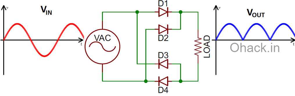
Below is an example power supply circuit
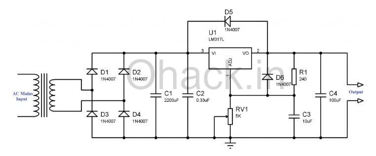
Regulated Power Supply DIY Project
In this project, we will make a regulated power supply that will make our project more efficient. We will not prepare a circuit for our project as above. We will try to make something which is less expensive that does not require much labour.
At the same time, we will not deal directly with the mains voltage. AC-DC conversion adapters will do this job. Adapters consist of parts such as transformers, diodes, capacitors that can perform the above-mentioned operations.
We will also use a voltage regulator board for setting the output voltage value.
The voltage regulator boards are the cards that can output the DC voltage to a certain voltage value. We will use a voltage-reducing board for this project, even though they are differentiated.
There are also cards on the market that can both increase and decrease the DC voltage. In this project, we will make use of an LM2596 voltage regulator board which is available at a very reasonable price.

LM2596 Voltage Regulator
- Input voltage range: 4-40 v
- Output voltage range:1.25V -37V
- Voltmeter precision: ± 5%
You can make changes to all materials in this project; your changes will determine the general characteristics of your power supply. The card we use reduces the voltage on to a voltage value depending on the setting. In other words, the voltage value of the source we will feed the card will cause a change in the maximum voltage that we will receive on the card.
If we supply our card with a 12-volt adapter, our output will be between 1.25 – 12 V.
In this section, you can also choose materials based on your budget or needs. By using the adapters we use in our homes, you can feed your card at no extra charge. Metal case power supplies, power supply in your old computer, or laptop adapters are also preferable.
There are many options for covering; we will use the plastic cover for this project. At the same time, we will add a digital voltmeter-ammeter to our box to monitor the amount of voltage and the current value of our source.
As I said, by revising all these materials as you wish, you can make a project with different features and costs.
Materials
Project Box (You can choose other alternatives for boxing.)
Mini Adjustable 3 A Voltage Regulator Board
Adapter / Power Supply (You can select a source that can provide a voltage between 4-35 V.)
Bourn Jack (Choose two jacks of different colours as we will output ‘+’ and ‘-‘.)
The above materials are used for this project. You can change these materials. We have included the Amazon link of the product mentioned above.
Ohack.in is a participant in the Amazon Services LLC Associates Program, an affiliate advertising program designed to provide a means for sites to earn advertising fees by advertising and linking to amazon.in
NOTE: Soldering will be required when performing the electronic assembly of the project. Therefore, besides these materials, you also need to have materials such as soldering iron and solder wire.

AdraXx 6 In1 Electric Soldering
Connection Diagram
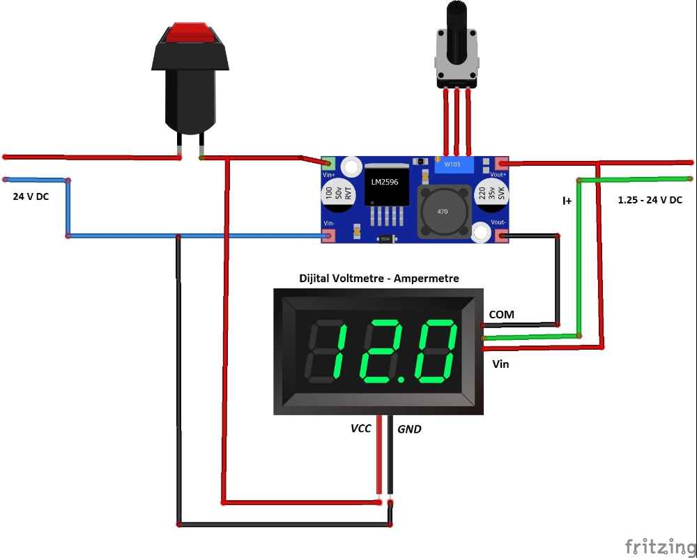
NOTE: Our voltmeter-ammeter works in a range of 4.5 – 30 volts. You can use this diagram for feeds up to 30 volts. If you use a 30+ V source, use the output voltage to feed the panel.
The construction phase
According to the dimensions of our parts, we will create suitable spaces for mounting on the box. You can use a hand drill for doing this. Different methods can be applied to different surfaces. We assemble switch, voltmeter-ammeter, jacks and potentiometer elements in our box.
Remember to drill a hole in the side of the box for the cable from the adapter/power supply to which we will feed our card.
In electronics assembly, we start by removing the trimpot or trimmer potentiometer on the voltage regulator board. In this part, we use our soldering iron carefully and remove the parts where the pot is soldered by heating.
We will connect our 10K potentiometer to where the legs of the pot are attached. Since these operations take place in a small space, be careful to avoid a short circuit caused by soldering.
The ‘IN +’ and ‘IN-‘ sections on the board show where to connect the + and – poles of the source. We cut the adapter at the end and solder the + and -cords here.
When you cut it, the black cable is ‘-‘. You can also test using a multimeter. If you prefer to use your adapter as a plug-in, you can add a female power jack to the box. So instead of using a fixed adapter in the box, you can remove it from the power supply when you’re done.
Make Voltmeter-ammeter, switch and jack connections according to the given diagram after the electronic assembly of the parts is completed. Remember to pay attention to the card while closing the box
You have made a mini regulated power supply that you can output according to the supply voltage. You can also set and provide appropriate voltage value in your projects With a maximum current rating of 3A, it will work efficiently in hobby work.
After completing the project, you can test the value using a multimeter. If you notice significant differences here, you can make adjustments using the voltage correction pot on the back of your voltmeter.
Regulated Power Supply Prices
The ready-to-sell power supplies come in a wide price range according to the current and voltage values they can provide. A regulated power supply of 0-30 V 5 A is around 8000 rupees in India, while the price of a power supply that can deliver a 2 A output of the same voltage is approximately 6000 INR.
Although power supplies with 0-30 V output voltage are the most preferred sources, regulated power supplies with much higher values are also available on the market. There are also kits which contain the necessary materials for the regulated power supply such as printed circuit board, circuit elements, and box. The price of the 1.25V-12V adjustable power supply kit is approximately 2000 INR.
Of course, these prices are constantly changing so make sure to check the latest price by clicking on the link below.
Although the preset power supplies have advantages in terms of both function and appearance compared to DIY one. They are expensive in terms of cost. The cost of the power supply we have made in this project is 1500-2000 INR depending on the adaptor to the adapter.
If you use the adapters from your home, have the spare cover and only use the voltmeter, the cost will be further reduced. A much more affordable budget product can be made by waiving certain features in this project. The cost will vary entirely according to your preferences.

DIY Kit Adjustable Regulated Voltage 1.20V-12V 2W Power Supply Module