
Table of Contents
In this post, we will learn about the diode. What are the types of the diode and what are their uses?
What is the diode?
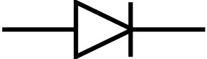
A diode is a two-pronged circuit element made of semiconductor materials that allow the electric current to pass only in one direction. The circuits are indicated by the following diode symbol:
The circuit symbol of the diode
The diode has two legs, anode and cathode.
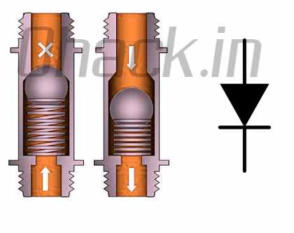
The diodes conduct current only from the anode to the cathode. For example, the diodes act as a valve on a pipe.
We can think of diodes as check valves for electric current.
History of Diode
Thermionic diodes (also known as vacuum tubes or lamps) and solid-state (semiconductor diodes) diodes were developed separately in the early 1900s.
These circuit elements were initially used as radio detectors. These radios were used for the detection of pulses such as Morse code from a modulated wave instead of sound transmission, unlike the radios we know today.
Thanks to the presence and absence of these pulses and the length between them, an operator was able to translate a message generated by Morse code into the text. For the detection of these pulses, diodes were used because of their non-linear voltage-current characteristics.
In 1873, Frederick Guthrie discovered the basic principle of the thermionic diode by observing that a positive charge could discharge without touching a grounded hot metal near a positively charged electroscope.
The same process did not occur when the electroscope was negatively charged, indicating that the current was flowing in only one direction. In 1880 Thomas Edison rediscovered the same principle independently during his experiments with light bulbs. About 20 years later, John Ambrose Fleming discovered that the phenomenon Edison discovered and called the Edison Effect or thermionic emission could be used as a sensitive radio detector.
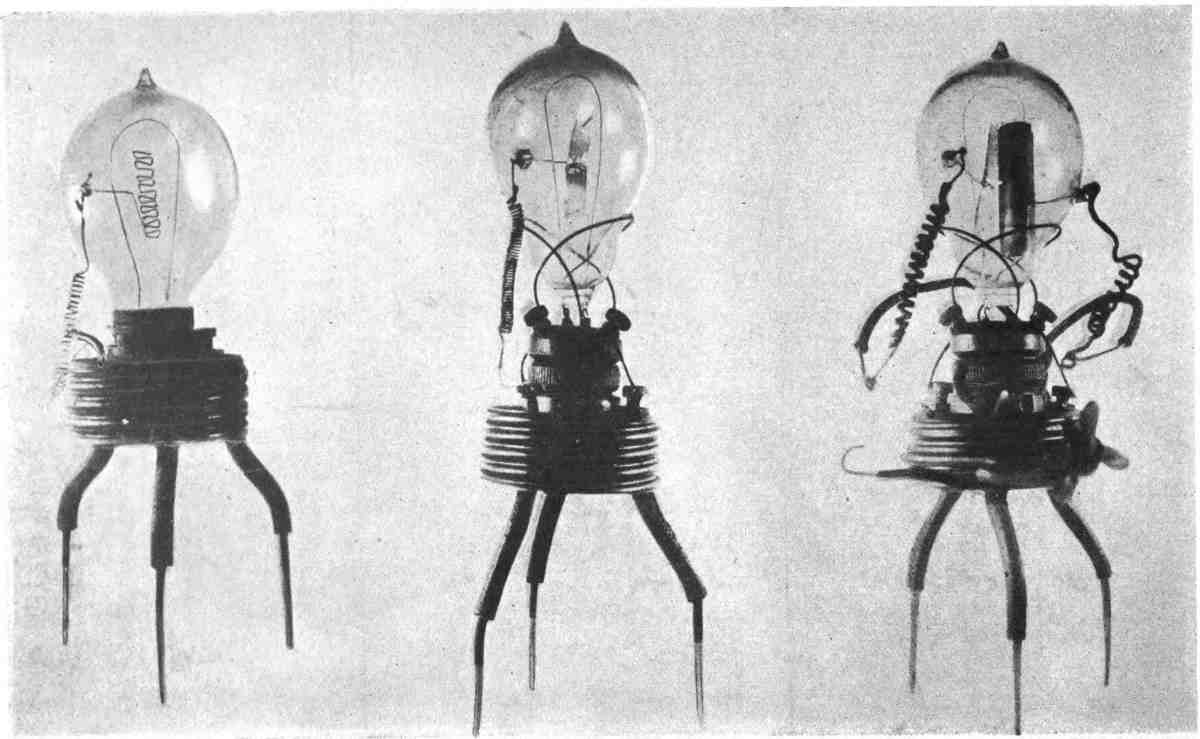
First Fleming Tube prototypes produced in October 1904 (source: https://en.wikipedia.org/wiki/Fleming_valve#/media/File:Fleming_valves.jpg )
In 1874, German scientist Karl Ferdinand Braun discovered the unidirectional transmission of crystals and patented it in 1899. Copper oxide and selenium rectifiers were developed for power applications in the 1930s.
Structure, Properties and Characteristics of Diode
Diodes are obtained by combining two different semiconductor materials, p-type and n-type. As we have mentioned in our transistor guide, semiconductor materials do not normally transmit electrical current.
In order to obtain P-type and n-type semiconductor material, semiconductor materials such as silicon or germanium are subjected to a process called doping.
Positively charged “holes p are found in p-type materials and negatively charged electrons in n-type materials. When we put these two items together, a structure like the following appears:
The diode is formed by the combination of P and N-type semiconductors.
As we can see in the picture when the positive voltage is applied to the anode end and a negative voltage is applied to the cathode end (this is called forward polarization).
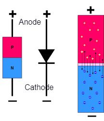
The positive charges in the p-type semiconductor material can move towards the negative loads of the n-type semiconductor so that the electric current through the diode transition is possible.
In the case of reversing the voltages (reverse polarity), there will be no load movement, so that no electric current will flow through the diode.
Diode Characteristics:
It is possible to understand the behaviour of an electronic circuit element, ie it is characteristic by looking at the current-voltage graph.
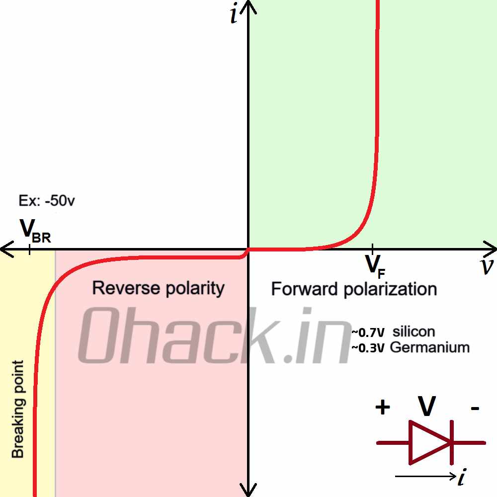
Current-voltage graph showing the characteristic of the diode
When we read this chart, it gives us the following basic information:
The diode must reach the threshold voltage indicated by Vf in order to conduct current while operating in the forward polarization zone. Generally, this value is around 0.7V for silicon diodes and 0.3V for germanium diodes.
The diode is current proof up to the maximum reverse voltage indicated by Vbr in the reverse polarity zone. When this value is exceeded, the diode is now in the breaking zone, that is to say, the current flows through the diode in the opposite direction. For example, this value is 50V for the 1N4001 diode.
Due to their different characteristics, diodes are used in electrical and electronic circuits for different purposes. For example, Zener diodes are diodes designed to work in the breaking zone.
Diode Uses:
Rectifiers
The first circuit type that we can give examples of the use of diodes is rectifiers. The rectifier is the name of the circuit used to convert AC voltage to DC voltage.
Half Wave Rectifier:
As we know, AC voltage varies between negative and positive with certain periods. The DC voltage is on the positive or negative side only. It is possible to establish a circuit in this way by making use of the diode’s ability to conduct current in one direction:
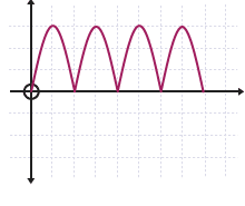
The circuit thus established is called a half-wave rectifier. Since only the positive part of the AC voltage passes through the diode, the voltage on the load will be as follows:
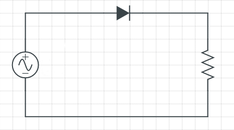
Half-wave rectifier circuit consists of a single diode.
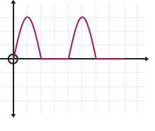
Half-wave rectifier output
What is Bridge Diode (Full Wave Rectifier)?
As you will notice from the circuit name and waveform, we can only benefit from half of a full cycle. To benefit from the full-wave bridge rectifier (full-bridge rectifier), we need to establish a circuit.
There are 4 diodes in the bridge rectifier circuit. Two diodes are in the positive part of the wave, while the other two diodes are in the negative part. Thus, we benefit from both the positive and negative part of the AC voltage.
Diodes are not only used in AC to DC conversion in power circuits. Different types of diodes are available for different purposes. Some of these are LED, Zener diode and Schottky diode.
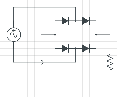
Bridge rectifier circuit consists of four diodes.
Bridge rectifier output
What is LED Emitting Diode (LED)?
Light Emitting Diode is an abbreviation of the initials of LED, is one of the most commonly used diode types in our daily lives.
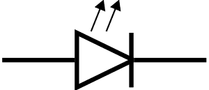
As they are used in the power and status indicators of our electronic devices, they are also frequently used for lighting purposes because of their efficiency. The circuit symbols are as follows:
LED circuit symbol
What is the Zener Diode?
The Zener diode functions as a standard diode when connected normally. In case of reverse connection to the circuit, they do not conduct current up to the level called Zener Voltage, and when this voltage is exceeded, start transmitting.
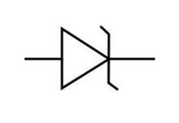
Thanks to this feature, Zener diode is used in power supply regulator circuits. The circuit symbols are as follows:
Zener diode circuit symbol
What is a Schottky Diode?
We learned that diodes are elements that transmit current in only one direction. As the current flows over the diode from the anode to the cathode, the voltage of the diode is reduced by a certain amount.
This amount of decrease is generally 0.7V in standard silicon diodes. In Schottky diodes, this value is much lower.
Also, some standard silicon diodes (eg 1N4007 ) cannot operate quickly enough at high frequencies. The Schottky diode can be used in this situation.
In spite of all these advantages, Schottky diodes have a disadvantage: Although the diodes only conduct current from the anode to the cathode, a certain amount of leakage current is transmitted in the opposite direction.
The leakage current values of Schottky diodes are much higher than silicon diodes.
Schottky diode circuit symbol

What is Laser Diode?
We have determined that diodes are made of semiconductor materials. There are two types of semiconductor materials: n-type with electrons and p-type semiconductors with positively charged “holes”.
These two semiconductors are combined to form a diode:
When the diode is biased in the normal forward state (positive to the anode, negative voltage applied to the cathode), electrons moving from the negative terminal of the power supply will want to go to positive voltage.
In this case, there will be a transition from N-type material to p-type material. The resulting energy is released as a photon.
Since a reflective coating is used at the point where the P and N materials meet, this photon emerges as light. By combining the resulting light with a lens, the laser light is obtained.
What is Photodiode?
A photodiode is a semiconductor circuit element that converts light into electrical current. The photons are absorbed by the photodiode and transformed into an electric current.
The solar panels we use are photodiodes with a very large surface.
Other Diode Types:
- LED Diode
- Zener Diode
- Schottky (Shotki) Diode
- Laser Diode
- Crystal Diode
- Tunnel Diode
- Photo Diode
- Varactor Diode
- Microwave Diode
- Gunn Diode
- IMPATT Diode
- Pin Diode
- Bridge Diode
- Silicon Diode (eg 1N4001 and 1N4007)
- Germanium Diode
- Screwed Diode
- Single Diode
- Bead Diode
- Dual Diode
The diodes are used as voltage regulators, reverse polarity protection, logic circuit gates, bypass circuits in series-connected solar panels and protection against voltage splashes in inductive circuits.